Benefits of the Rock Shear Test:
- Accurately measures the effective cohesion and effective angle of internal friction of rock.
- Useful for design of rock slopes or excavations
- Good for computing the capacity of deep foundations and drilled shafts with rock sockets.
While the engineer needs to know the shear strength of rock for design of slopes and bearing capacity of deep foundations, it is difficult, if not impossible, to measure it in the laboratory. Rock quality designation (RQD) does not correlate with shear strength. As a result of the difficulty of measuring rock strength, engineers have been ultraconservative with their designs. Schmertmann and Hayes (1997) show that engineers use a factor of safety often greater than 10 for design of vertical capacity of deep foundations in rock based on O-cell tests (Figure 1).
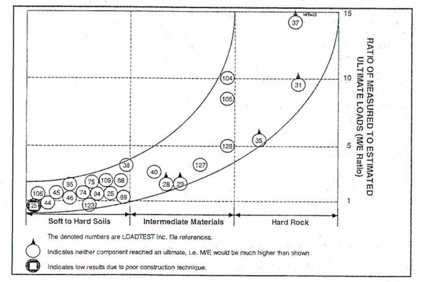
Figure 1: Engineers underpredicting rock capacity of drilled shafts
Dr. Dick Handy developed a rock borehole shear test (RBST) device to measure the shear strength properties of rock (Failmezger, White, Handy, 2008). While its testing principles are similar to the soil borehole shear test, a hydraulic pump pushes the shear plates of the robust shear head outward into the rock to a maximum normal stress of 80 MPa. After locking in the normal stress, a hydraulic piston at the surface pulls the shear head upward shearing the rock with a maximum stress of 50 MPa. Figure 2 shows the driller and helper lowering the rock borehole shear head into the borehole and Figure 3 shows the rock shear head, hydraulic shearing piston and hydraulic pump/control box.
Figure 2: Lowering the rock shear head into the borehole
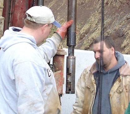
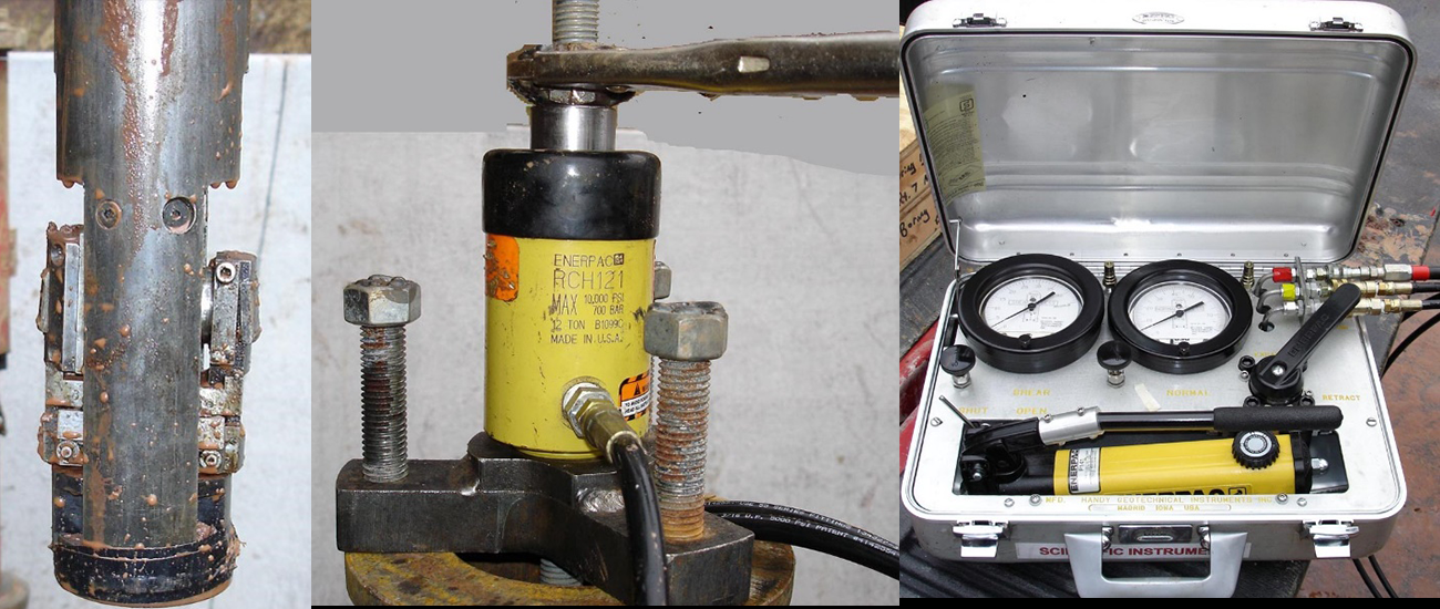
Figure 3: Rock borehole shear test equipment
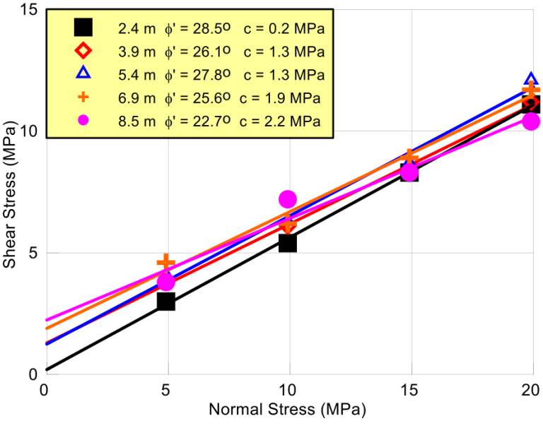
The field crew threads the hydraulic lines connecting the pump to the shear head through the wireline casing, protecting the hydraulic hoses. After the driller cores the rock with an NX core barrel, he/she lowers the rock borehole shear head that is attached to the wireline casing, which serve like drill rods to the desired test depth. After the engineer applies the first normal stress increment to the rock (at least 5 MPa to ensure that the plates fully embed into the rock), he/she slowly hydraulically pulls the shear head upward and measures the maximum shear resistance as the rock breaks. He/she retracts the shear plates to their fully closed position. If the rock smears rather than chips, which is usually the case for shale and siltstone, the engineer rotates the shear head 45o and tests fresh rock at a higher normal stress. He/she continues to shear the rock for a total of four (4) sets of normal/shear stress data points. If the rock chips, the driller will need to remove the shear head and the engineer clean it. The driller will then lower the shear head to a depth of 50 mm or 2 inches above the previous test depth to make sure that fresh rock is tested. Typical rock shear results are shown in Figure 4.
Figure 4: Typical Rock Shear Test Results
The rock shear test has a great potential for improving the design of drilled shafts socketed into rock. Osterberg load tests will be needed to evaluate any scaling effects.
Rock slopes generally fail as block failure surfaces. Failures can be along existing joints and through intact rock. The shear strength of joints can be modeled as having a frictional resistance (i.e. tan(Φ)) and a cohesive intercept of zero, while the shear strength of intact rock can be modeled as having a frictional resistance and a cohesive intercept. The engineer or geologist should map the profile of the rock, delineating the zones where the potential failure surface is in the direction of existing joints and where the failure is either through intact rock or against the joints. Based on the rock borehole shear test results, the shear strength values are then assigned to each layer. Presented as Figure 5 is diagram showing assigned shear strength parameters for suggested rock slope stability design approach.

Figure 5: Assigning rock shear strengths for a slope